PICマイコンを使用し、ステッピングモーターを動かします。
次のようなステップになります。
- 必要なパーツを揃える
- ブレッドボードに回路を作成する
- MPLABのプロジェクトを作成する
- C言語でプログラムを作成する
- MPLAB X IDEでプログラムをPICに書き込む
- PICをブレッドボードに取り付けてステッピングモーターを動かす
1. 必要なパーツを揃える
必要なもの
- PICkit3 * 1 Amazon ANBE PIC プログラミングキット PICKIT3互換品 PIC マイコン ライター
- PIC16F84A * 1 秋月電子通商 PIC16F84A-20I/P
- 抵抗 3.3kΩ * 4 秋月電子通商 カーボン抵抗 1/4W 3.3kΩ(100本入)
- セラロック 20MHz * 1 秋月電子通商 セラミック発振子 (セラロック) コンデンサー内蔵タイプ 20MHz
- ダーリントントランジスタ * 4 秋月電子通商 ダーリントントランジスタ TTD1509B 80V2A
- ダイオード * 4
- 2相ユニポーラステッピングモーター * 1 秋月電子通商 コパルステッピングモーター SPG20-1332
- ブレッドボード用DCジャック * 1 秋月電子通商 ブレッドボード用DCジャックDIP化キット
- DC12V ACアダプター * 1 秋月電子通商 超小型スイッチングACアダプター12V1A AD-K120P100
- ブレッドボード * 2 秋月電子通商 ブレッドボード EIC-801
- ジャンパワイヤー * n 秋月電子通商 ブレッドボード・ジャンパワイヤセット
- ブレッドボード・ジャンパーワイヤ * n 秋月電子通商 ブレッドボード・ジャンパーワイヤ 14種類 × 10本
- 電池ボックス * 1 秋月電子通商 電池ボックス 単3×3本
- クリップ付きコード * 6 秋月電子通商 小型クリップ付コード 5色 45cm 5本入
補足
- 参考資料 PIC16F84A Documents
2. ブレッドボードに回路を作成する
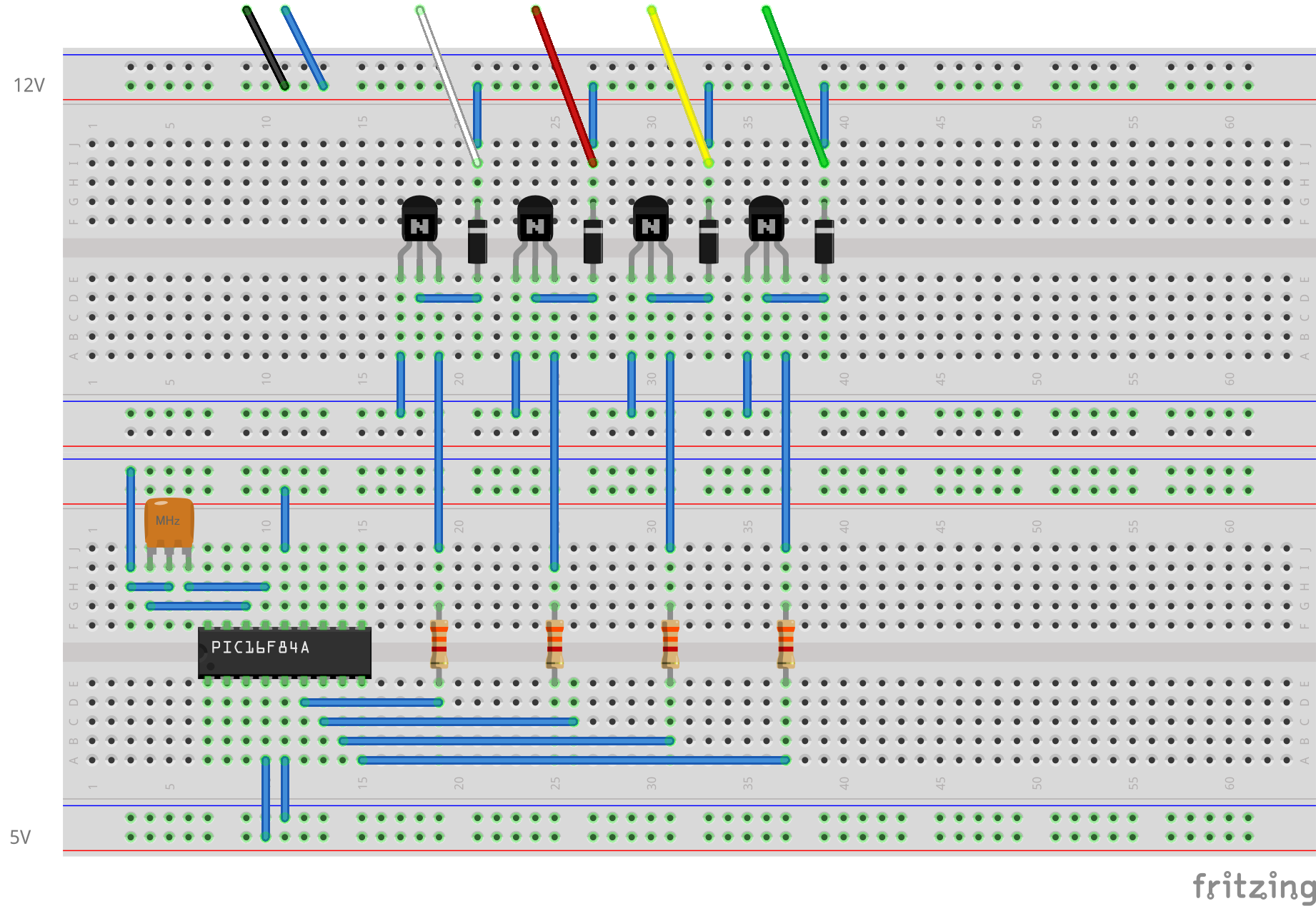
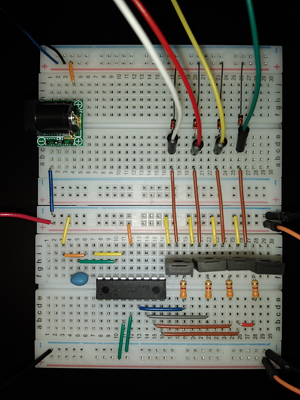
秋月のPICステッピングモータドライバキットの回路図を参考にブレッドボードに回路を作成します。
回路図


3. MPLABのプロジェクトを作成する
前回と同様にプロジェクトを作成します
名前は、pic_0005_motorとします。
4. C言語でプログラムを作成する
制御方式は、1相励磁とします。
A相、B相、Aバー相、Bバー相、A相の順に励磁することでモーターが回転します。
Source code
1 | |
解説
PICとステッピングモータの接続は以下のとおりです。
- RB0がA相
- RB1がB相
- RB2がAバー相
- RB3がBバー相
順に励磁することでモーターが回転します。励磁の切り替えは10[ms]としました。
今回選択したステッピングモーター(SPG20-1332)は1回転480ステップなので、1周するのに4800[ms]かかります。
5. MPLAB X IDEでプログラムをPICに書き込む
省略
6. PICをブレッドボードに取り付けてステッピングモーターを動かす
今回は電源に注意してください。
モーターの黒と青は12Vに接続しますが、PICは今までどおり電池ボックスに接続してください。